Seamless Pipe with PWHT Designation
A Post Weld Heat Treatment (PWHT) designation for Seamless Pipe? Is that crazy?
It may not be standard procedure, but it isn’t crazy. I like to specify PWHT for seamless pipe materials when the pipe specification service calls for PWHT.
Let’s take a look at a common scenario where calling out Post Weld Heat Treatment (PWHT) designation for Seamless Pipe could have saved a big headache. In the example picture a new circuit was added to an existing circuit with a required PWHT designation due to service requirements. Since the seamless pipe did not have a PWHT designation, the welded pipe added during an expansion did not receive the required post weld heat treatment. The new pipe section that did not receive PWHT quickly experienced in-service issues.

Stop Designing with Deadlegs
Are you unintentionally adding deadlegs to your piping designs?
We all have hopes and dreams but your "future expansion” may actually be a major hazard due to the susceptibility of corrosion in these areas. Please be careful with piping headers and branched connections that are intentionally blinded off after construction to prepare for a future expansion. Many times the expansion plan never materializes and the associated deadleg is never properly accounted for in the site’s integrity program.
What’s wrong with deadlegs? They get hardly any flow and experience higher corrosion rates than the rest of the piping system.

B16.5 Blind Flanges as Reducers
Ever see ASME B16.5 blind flanges as reducers?
Just throw any pipe in a standard ASME B16.5 blind and you’re good-to-go, right?
No. That “standard” ASME B16.5 blind flange may not be “standard” once you decide to start drilling holes in it. Many times ASME B16.5 blind flanges used as reducers include pipes larger than allowed in B16.5 without a reinforcement calculation. Please make sure your facility has proper documentation for ASME B16.5 blind flanges used as reducers.

Calculate B16.9 Elbows by Outer Diameter (OD)
Like to use ASME B16.9 Elbows as main pressure containing components? Please remember to treat them as seamless pipe and to calculate the required thickness by outer diameter. This means using Appendix 1-1 instead of UG-27 for internal pressure in Division 1.
I see off-the-shelf ASME standard flanges and pipe fittings often used as main pressure containing components in pressure vessels and heat exchangers. I’ve noticed the biggest variance in approach when I investigate ASME B16.9 Elbow calculations. Some design engineers believe that ASME B16.9 Elbows do not require any calculations at all. Others calculate ASME B16.9 elbows using UG-27. Very few use Appendix 1-1.
Notice that Appendix 1-1 may require extra thickness compared to UG-27. Please refer to UG-44 for more information regarding the calculation of standard flanges and pipe fittings.

“Welded and Seamless Pipe” Product Form
Let’s talk about my favorite product form “Welded and Seamless Pipe”.
Is it Welded? Is it Seamless? Is it Both? Wait, that’s impossible…
Well then what is a “Welded and Seamless Pipe”? I have no idea. What I do know is that there is a big difference between how welded pipe and seamless pipe are handled when it comes to ASME Code calculations. You need to know exactly which version of the material you have before performing calculations or there is a good chance you will be making a big mistake.
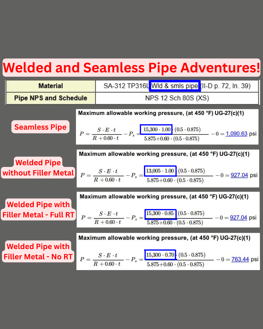
Let’s take a look at SA-312 TP316L, which includes the seamless and welded pipe product form in the same specification.
Seamless: No need for a longitudinal weld joint efficiency factor in the allowable stress. Double-check to make sure the allowable stress reflects this.
Welded Pipe Made without Filler: The longitudinal weld joint efficiency factor needs to be included in the allowable. Notice the allowable is (15,300 x 0.85 = 13,005). There is no need to count this twice and multiply by 0.85 again in the joint efficiency value.
Welded Pipe Made with Filler: The joint efficiency factor was not included in the allowable so it needs to be taken into consideration in the joint efficiency value itself. Keep in mind that the joint efficiency value may be lower than 0.85 depending on the radiography performed.
