
Integrity Operating Windows (IOWs) Resolve Operator Conflicts
Engineers in most companies have to perform tasks way outside of their official job description. I often find myself working as a mediator helping in conflict resolution situations.
Why does the B Shift Operator run at the exact same equipment at different temperatures and pressures than the A Shift Operator? I can’t tell you why. What I can tell you is that an up-to-date Corrosion Control Document (CCD) with well defined Integrity Operating Windows (IOWs) is all that I need to tell you which operator is correct.
I’ve seen operators ignore visual and audible alarms for high limit switches during their entire shift. Every. Single. Shift. A well defined IOW helps me explain to the operator why equipment should be run under specific conditions. Conflict resolved!

Using Multiple Corrosion Allowances
Don’t be afraid to use two different corrosion allowances in your static equipment design. It’s no big deal!
Many processes create two (or more) streams with different corrosion rates. Assigning the same corrosion allowance for each of these stream sections in your equipment may not make sense.
The designers bidding on your new static equipment have fancy software that easily handles multiple corrosion allowances. This means calculating equipment required thicknesses using multiple corrosion allowances adds 𝐧𝐨𝐭𝐡𝐢𝐧𝐠 to the engineering design cost. U-forms clearly report multiple corrosion allowances for each shell section so adding multiple corrosion allowances to U-Forms is not a problem either. Mechanical integrity programs will split the equipment sections into the appropriate corrosion loops anyway. In fact, your mechanical integrity program will 𝐠𝐫𝐞𝐚𝐭𝐥𝐲 𝐚𝐩𝐩𝐫𝐞𝐜𝐢𝐚𝐭𝐞 assigning the appropriate corrosion allowance to sections that have higher corrosion rates.
I have found that many times mechanical integrity departments are forced to live with bad decisions made with the initial equipment design. Inspecting the same equipment over-and-over again is much more expensive than designing the equipment correctly in the first place. Metalmark Engineering is not afraid to use multiple corrosion allowances in their designs; you shouldn’t be afraid either.
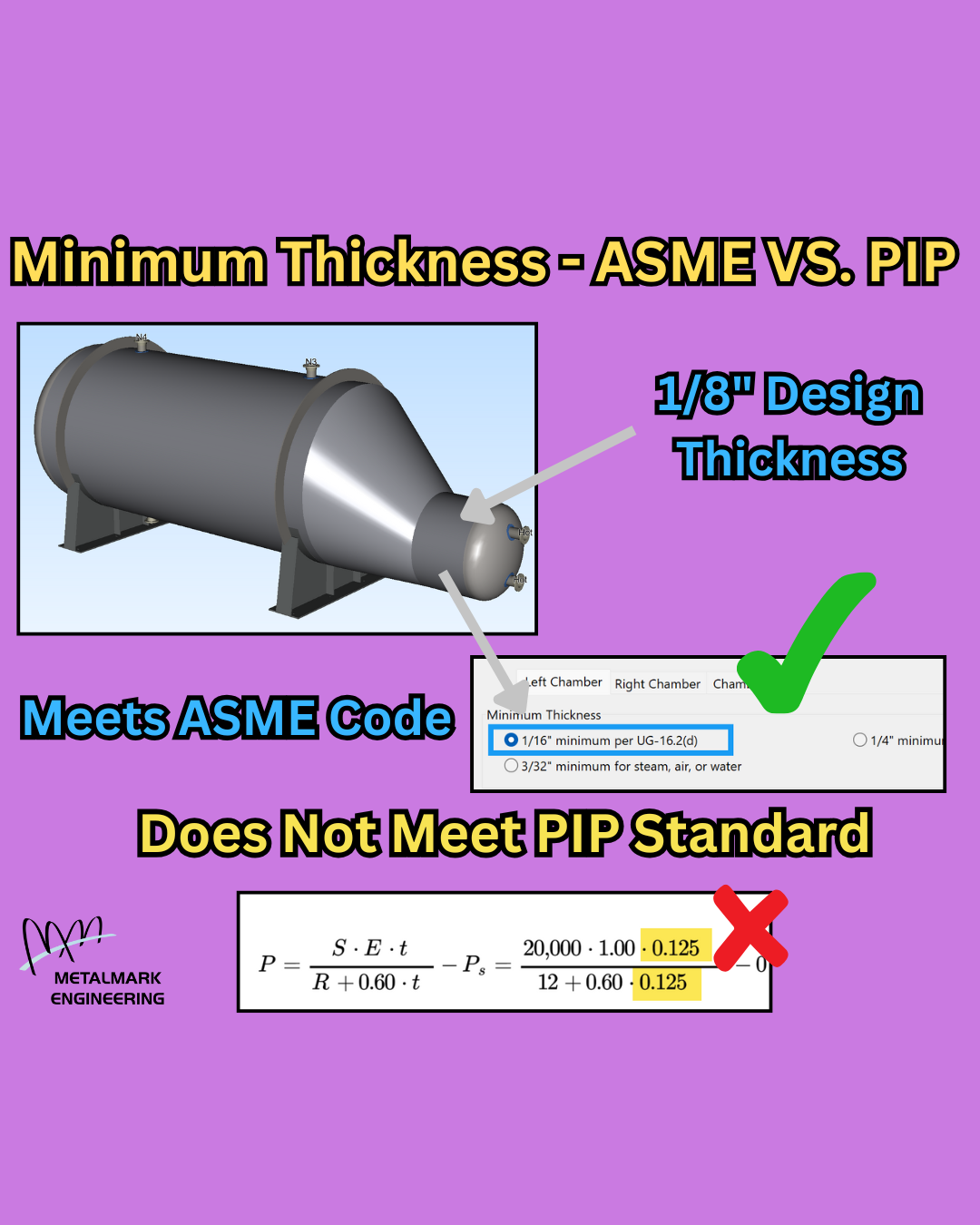
Minimum Thickness - ASME VS. PIP
Valid ASME Code designs rejected by Owner/Operators? It happens all the time when facilities enforce their own specifications, such as Process Industry Practices (PIP) specifications, on top of ASME Code rules.
Let’s take a look at a low consequence vessel designed with a ⅛” port cylinder thickness. Yes, the ASME Code allows for thicknesses as low as 1/16” per UG-16.2(d). However, the PIP Specification requires 3/16” minimum corroded thickness for all heads and shells. This means that facilities governed by the PIP Specifications need to adhere to the 3/16” minimum thickness and NOT the 1/16” thickness per ASME Code.
I love helping Owner/Operators enforce their own specifications because well defined specifications can help ensure facilities run safely and efficiently. Not sure where to start? Metalmark Engineering specializes in creating and maintaining the specifications for facilities just like yours!

Outdated Nuclear Industry
Nuclear, I get it. You are trying to go fast. But please be like the rest of the world and consider designing with the latest Codes and Standards.
Yes, you can technically use that same 1970’s heat exchanger design in your brand new plant, but why would you want to? New designs will perform better and last longer because they incorporate the latest design rules with M-Star CFD and modern manufacturing techniques.
Did you know that your old heat exchanger designs pre-date the UHX rules? I’ve seen 𝐜𝐫𝐚𝐳𝐲 𝐭𝐮𝐛𝐞 𝐬𝐭𝐫𝐞𝐬𝐬𝐞𝐬 in fixed exchangers because the old design never checked for tube stress. I’ve seen 𝐞𝐱𝐭𝐞𝐫𝐧𝐚𝐥 𝐩𝐫𝐞𝐬𝐬𝐮𝐫𝐞 𝐧𝐨𝐭 𝐜𝐨𝐧𝐬𝐢𝐝𝐞𝐫𝐞𝐝 in floating tubesheet exchangers when it should have governed the maximum shell side pressure. I’ve seen nozzles 𝐭𝐨𝐨 𝐜𝐥𝐨𝐬𝐞 𝐭𝐨 𝐭𝐡𝐞 𝐭𝐮𝐛𝐞𝐬𝐡𝐞𝐞𝐭 in u-tube exchangers which should have failed UHX-4(i)(1).
Going fast doesn’t have to mean using your old, bad designs. Unsure about your old design drawings and calculations? Metalmark Engineering offers 3rd party view to give your team peace of mind while going fast.

AI Generated FEA Results
The era of AI generated FEA results is here!
I like comparing FEA results to closed-form solutions because they help validate each other.
I 𝐥𝐨𝐯𝐞 comparing AI generated FEA results to closed-form solutions because they give me a good laugh.
Thankfully the trend of getting AI generated FEA results through regulators appears to be over. In Canada Annex J of CSA B51 spells out the exact requirements regarding using FEA in equipment design. A couple of effective requirements stand out to me.
J.2) FEA may be used to support equipment design where the configuration is not covered by the available rules.
Many times AI generated FEA is submitted for simple designs already covered by ASME Division 1 and Division 2. This rule prevents FEA-only submissions for simple designs.
J.3) FEA report shall be certified by a Professional Engineer
The entire point of creating AI generated FEA results is to circumvent engineering costs. This rule prevents submissions from unqualified actors putting the public at undue risk.
While your regulatory jurisdiction may not have any requirements regarding the use of FEA, I strongly support considering these two requirements for internal rules. Please be careful when selecting a fly-by-night unlicensed FEA firm with pricing that is too good to be true.

Mixing Units in Drawings Rejected by Regulators
Don’t let this simple mistake cause your design drawings to be rejected by regulators.
Modern design drawings often use US Customary and metric units interchangeably. Not a big deal for experienced designers and fabricators that are used to seeing both. However, there are a few specific cases I look for because I’ve seen them rejected by regulators.
One of those is when 6mm fillet welds are applied to ¼” nozzle reinforcement pads. A 6mm weld works on a 6mm plate. A 6mm weld does not work on a ¼” plate due to the UW-16(d) weld size check. The difference between 6mm and 6.35mm may seem trivial to fabricators but it is not trivial to regulators who check design drawings for this specific combination.
Did you know that 3rd party reviews help you execute projects faster? Metalmark Engineering checks your design drawings against your design calculations to give you the best chance to sail through regulatory review.

Expensive Hydrotests
Sometimes performing the ASME Code required hydrotest is deemed too expensive so Owner/Operators skip it.
One factor that may raise the cost of hydrotesting is if the hydrotest pressure is much greater than the operating pressure. The higher hydrotest pressure may require the fabrication of single-use components, supplying a special set of gaskets, and another PCC-1 Appendix O calculation.
One of the sad realities of the extreme cost-cutting associated with modern manufacturing is the loss of basic design principles. I’ve noticed that performing proof tests and leak tests instead of ASME Code required hydrotests is becoming increasingly popular in new vessel construction.
Authorized Inspectors (AIs) often assume a shop hydrotest was performed and never check the U-Form notes that clearly states otherwise. The “what can I get away with?” mentality rewards design engineers with promotions while operator roles become increasingly dangerous.

CMLs Showing Equipment Growth
Ever plot CML thickness and notice your piping or equipment growing over time?
This “reverse corrosion” phenomenon sweeping inspection departments can defile your data and give false impressions of real metal loss and corrosion rates.
How common are growth readings for CMLs? VERY. In fact, during Jeff Goldstein, P.E.’s latest webinar “Rethinking Piping Inspection Locations” he discussed a site with 12,000 of 40,000 CML readings showing growth over the last CML reading. That is 30% of readings showing a growth rate instead of an expected metal loss/corrosion rate. What you decide to do with these growth readings will have a big impact on maintenance and inspection plans moving forward.
Maybe there was an undocumented piping or equipment replacement.
Maybe the measuring device was not properly calibrated when the operator took CML readings.
Maybe the CML readings were entered into software or spreadsheets incorrectly.
Maybe the CML readings were taken in the wrong location.
Please spend some time trying to understand what is causing growth readings and act accordingly.

Verify Thicknesses Before Installing Equipment
Do you verify thicknesses before receiving your equipment?
The design calculations use NPS 8 Sch 120.
The fabrication drawings use NPS 8 Sch 120.
You received NPS 8 Sch 80 (XS).
So what happened? A drawing was misinterpreted and a fabrication mistake was made. Fabrication mistakes happen. Don’t compound those mistakes by not finding them until after installation. Using a 3rd party to verify that your as-built thicknesses meet or exceed your design thicknesses is a quick and important step you should implement before receiving your equipment to help improve your bottom line.
I like to use 3rd parties for thickness verification because they are excellent at communicating between fabricators and Owner/Operators during stressful projects. I trust Turnaround EPC for my 3rd party as-built thickness verification because of their excellent communication, fast service, and attention to detail.

Use ASME PCC-1 Appendix O to Fix Leaky Gaskets
Do you have an issue with leaky gaskets?
A lot of people message me complaining about leaky flange gaskets and wondering what kind of gaskets I recommend to help. The fact of the matter is that gasket quality and performance has never been better. I have found that many times the real problem is that the gasket was not considered during the design phase. Gaskets are an important part of flange design. Treat them that way.
Have you performed ASME PCC-1 Appendix O for your flanges?
An approach in ASME PCC-1 Appendix O can help you make sure your gaskets are being seated correctly. The gasket needs to be below the maximum permissible gasket stress, above the minimum seating gasket stress, and above the minimum gasket operating stress. In this example the minimum gasket operating stress is not being maintained at the operating condition.
Make sure you perform ASME PCC-1 next time you open up a pair of flanges.

Move Data from U-Forms into Spreadsheets for AI
Are you ready for AI? Your data is not.
One of the big themes of Reuters Downstream 2025 was the use of AI in maintenance and inspection. I found the concept of using AI for predictive analytics in maintenance incredibly intriguing. However, let’s not pretend that your important data is in a format that AI can actually use. You need to digitize your data.
Are your U-Forms sitting in a filing cabinet somewhere?
How about the historical measured thickness data from internal inspections? Are those values just floating around in PDFs?
What about the interesting information found during external inspections? Repairs? Rerates? Derates? FFS assessments? Wouldn’t you want all of that data digitized in a way that makes it easy for AI to pull from?
We all know that AI is the future but AI is only as good as the data you are feeding it. Consider yourself behind if the items listed above are not in a usable, digital format.

Towers Falling During Postweld Heat Treatment (PWHT)
Have you seen a tower fall during Post Weld Heat Treatment (PWHT)?
As crazy as it sounds I’ve seen this occur when PWHT is applied around the circumferential seams of tall towers in the field. The solution is often even crazier as Owner/Operators prefer expensive materials analysis and complex FEA calculations over simple explanations. The fact is the tower behaved exactly as expected as it was never designed to take such loadings at temperature.
So what is actually happening?
1 - The Wind case was not properly considered by the design engineer
2 - The Wind case in the Empty condition was not calculated
3 - The much lower allowable stress in the material at temperature was not considered
4 - Wind loads during PWHT create a large moment that the material was not designed to resist
5 - DOWN IT GOES!!!

Be Careful with RT-4 Vessels in Corrosive Service
I think it’s time we talk about “RT 4” vessels and heat exchangers. I see them everywhere in corrosive processes and highly consequential service and I really wish I didn’t.
So what is “RT 4”? Well “RT 4” simply means that “RT 1”, “RT 2”, or “RT 3” do not apply. It does not mean anything else specifically about what kind of weld inspection was applied to the vessel.
How much radiography or other weld inspection is applied to a vessel marked “RT 4”? Some? None? I don’t know, but probably not a lot. I personally assume that no weld inspection was performed unless proven otherwise. This is where I have a problem with “RT 4” vessels and exchangers. I don’t feel comfortable placing vessels and heat exchangers in service without having some sort of assurance regarding the quality of the welds. When I uncover the root cause of unplanned shutdowns too many times these “RT 4” vessels are to blame.
I consider the cost of maintenance and inspection in my designs and I do not believe any money is saved in the long run by operating “RT 4” vessels.

Mechanical Credit for Cladding
Are you getting the credit you deserve?
The ASME Code allows you to take mechanical strength credit for cladding in design calculations. Most design engineers do not take credit for cladding and end up purchasing a thicker shell than necessary.
Take a look at this simple internal pressure with cladding example:
Design P = 350 psi (2413 kPa)
Shell Material = SA-516 70
Cladding Material = SA-240 316L
MAWP from shell component: 343 psi (2365 kPa)
MAWP from cladding component: 40 psi (276 kPa)
MAWP from shell plus cladding: 383 psi (2641 kPa)
Using only the shell component for mechanical strength fails at the Design Pressure of 350 psi (2413 kPa).
Using the shell plus cladding for mechanical strength passes at the Design Pressure of 350 psi (2413 kPa).

Performing Proper Hydrotests After Tube Bundle Replacements
Are you performing proper hydrotests after Tube Bundle Replacements?
I’ve seen some interesting ways Owner/Operators try to save money on new equipment costs. Opting for leak tests and proof tests instead of performing ASME Code required hydrotests has become increasingly popular, especially when it comes to tube bundle replacements. The problem with not performing a full hydrotest at the fabrication shop is that the requirement to field hydrotest is hidden away as a remark at the end of the U-Form and is easily ignored.
Owner/Operators have not yet made the connection between the frequency of their tube bundle replacements and the lack of proper hydrotest for the tube bundles they are replacing. Properly hydrotested tube bundles will last longer. The most cost effective way to perform your hydrotest is most often at the fabrication shop. Please pay your fabricator for a full hydrotest.

Allowable Stress Rounding Rules Changed in 2007
Did you know that the rounding rules for allowable stresses in ASME Section II-D changed in 2007?
If you are anything like me you have to run a lot of calculations on older equipment. Making sure I use the correct allowable stress is not always a straightforward task. One ASME Code change I have to remember is to the rounding rules in the 2007 version of ASME Section II-D.
In this example using the latest allowable stress rounding rules results in an unconservative required thickness because the original design was calculated using a lower allowable stress. Please do not accidentally give yourself credit for the newer allowable stress rounding rules when re-calculating older equipment.

Missing Floating Tubesheet Calculations
Does your floating tubesheet heat exchanger have complete calculations?
I have been asked many times to check calculations for floating tubesheet heat exchangers only to find some of them missing. The calculation I see most often omitted is from the shell side pressure acting on the internal floating tubesheet components. The external pressure from the shell side often governs over the internal pressure from the tube side so checking this case is critical.
Many Owner/Operators will accept equipment for service without these calculations performed. Please double-check this case in your floating tubesheet heat exchangers.