
Division 2 Rules Save $ On Nozzle Design
Did you know you can design safer and save money using ASME Division 2 rules instead of Division 1?
There are many ways to take advantage of the higher allowables and more accurate numerical methods in Division 2. One such method to consider is using the Bildy Rules instead of Area of Replacement for nozzle design.
Take a look at this simple nozzle internal pressure case:
Design Pressure = 290 psi (2000 kPa)
Design Temperature = 475°F (246°C)
Nozzle Material = SA-106 C Smls Pipe
Nozzle Size = NPS 12 Sch 140
The Division 1 vessel does not pass the design condition of 290 psi (2000 kPa) @475°F (246°C).
The Division 2 vessel passes the design condition of 290 psi (2000 kPa) @475°F (246°C).
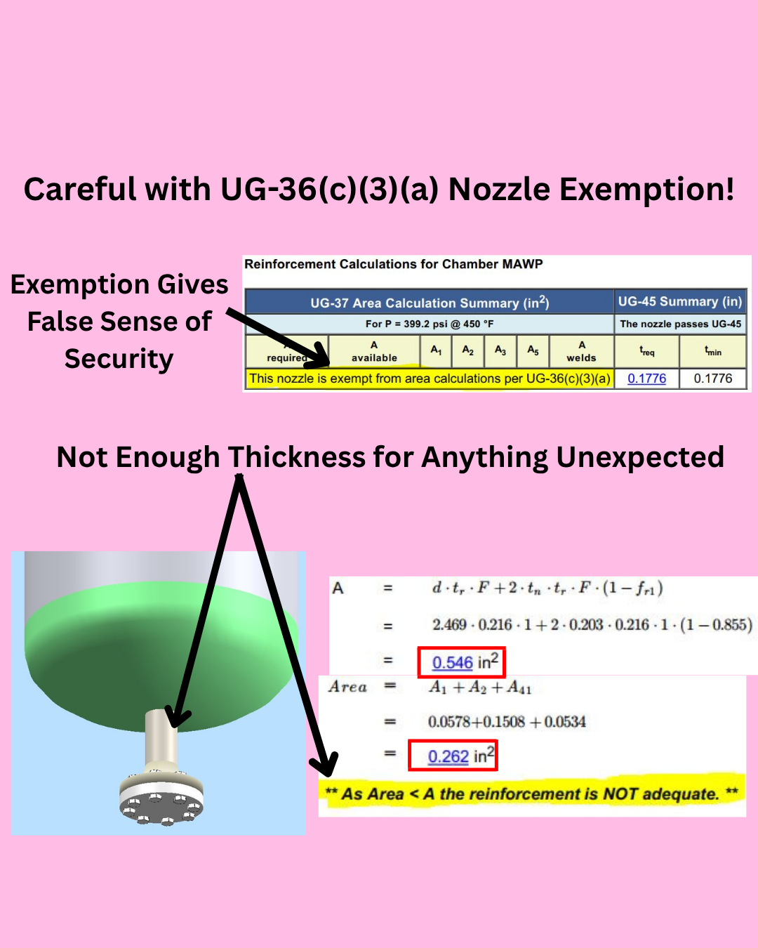
Do Not Use Calculation Exemptions on Important Process Nozzles
Do you use calculation exemptions on important process nozzles?
Yes, we all know nozzles under a certain size are exempted from the Division 1 nozzle area-of-replacement rules. That does not mean that you should use this exemption every time you can. Think very carefully about what each nozzle is used for and what the consequences of failure may be.
You may want to double-check exempted nozzles against another set of nozzle rules before finalizing your design. Are you around 90% of area-of-replacement? Fine. Are you around 50% of area-of-replacement like my example? You may want to add a little thickness to the nozzle. This is a bad place to try to save money on your design.
What if local corrosion is higher than the design corrosion?
There is no nozzle thickness to compensate for corrosion. Through wall corrosion is common.
What if nozzle loadings are higher than anticipated?
There is no extra thickness to handle pressure plus unexpected loadings.
What if an upset condition increases the process velocity?
There is no extra thickness to handle process erosion.
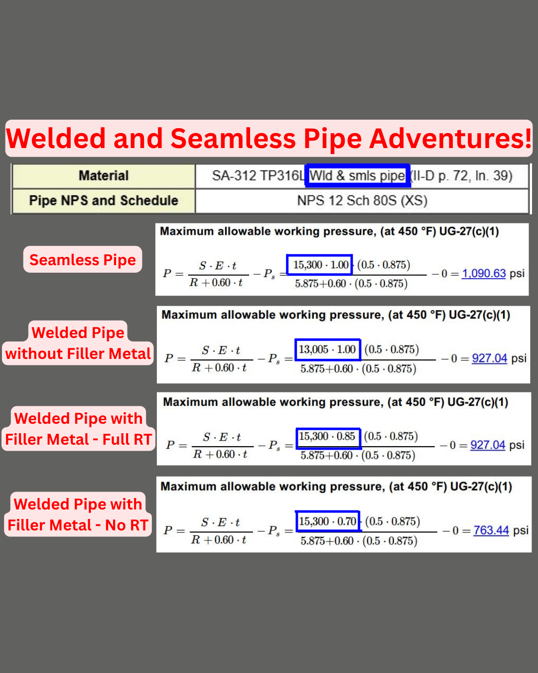
“Welded and Seamless Pipe” Product Form
Let’s talk about my favorite product form “Welded and Seamless Pipe”.
Is it Welded? Is it Seamless? Is it Both? Wait, that’s impossible…
Well then what is a “Welded and Seamless Pipe”? I have no idea. What I do know is that there is a big difference between how welded pipe and seamless pipe are handled when it comes to ASME Code calculations. You need to know exactly which version of the material you have before performing calculations or there is a good chance you will be making a big mistake.
Let’s take a look at SA-312 TP316L, which includes the seamless and welded pipe product form in the same specification.
Seamless: No need for a longitudinal weld joint efficiency factor in the allowable stress. Double-check to make sure the allowable stress reflects this.
Welded Pipe Made without Filler: The longitudinal weld joint efficiency factor needs to be included in the allowable. Notice the allowable is (15,300 x 0.85 = 13,005). There is no need to count this twice and multiply by 0.85 again in the joint efficiency value.
Welded Pipe Made with Filler: The joint efficiency factor was not included in the allowable so it needs to be taken into consideration in the joint efficiency value itself. Keep in mind that the joint efficiency value may be lower than 0.85 depending on the radiography performed.

LWN Forged Flanges Required Nozzle Calculations
Are you performing the required calculations for your LWN forged flanges?
LWN forged flanges are popular among Owner/Operators because the ASME Codes offer some calculation exemptions. However some Owner/Operators have started to believe that LWN forged flanges are exempt from all calculations. This is a dangerous trend as LWN forged flanges are not automatically acceptable at their designated ASME B16.5 flange pressure rating classification. Yes, LWN forged flanges do have some similar exemptions as ASME B16.5 flanges but a full nozzle calculation must still be performed at the nozzle-to-vessel intersection.
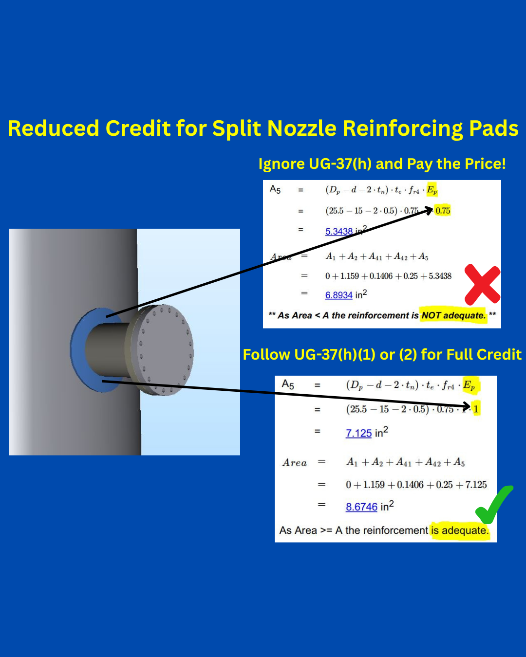
Penalty for Split Nozzle Pads per UG-37(h)
What’s worse than using segmental nozzle reinforcement pads to meet UG-37 area-of-replacement requirements? Only getting 75% credit for the pad area.
People ask me all time to review nozzle calculations and one mistake I often see is with split or segmental nozzle reinforcement pads with weld orientations lined up with the longitudinal axis and with no way to inspect them. I fail a lot of nozzles this way when the reinforcement pad does not give the design engineer the credit for the area that they expect.
That’s right. If you do not satisfy the requirements of UG-37(h)(1) or UG-37(h)(2), only 75% of your nozzle reinforcement pad area may be used in A5. This means that the design engineer needs to put some thought into the design of the reinforcement pad and weld.
Please refer to UG-37(h) for more information regarding segmental reinforcement pads.
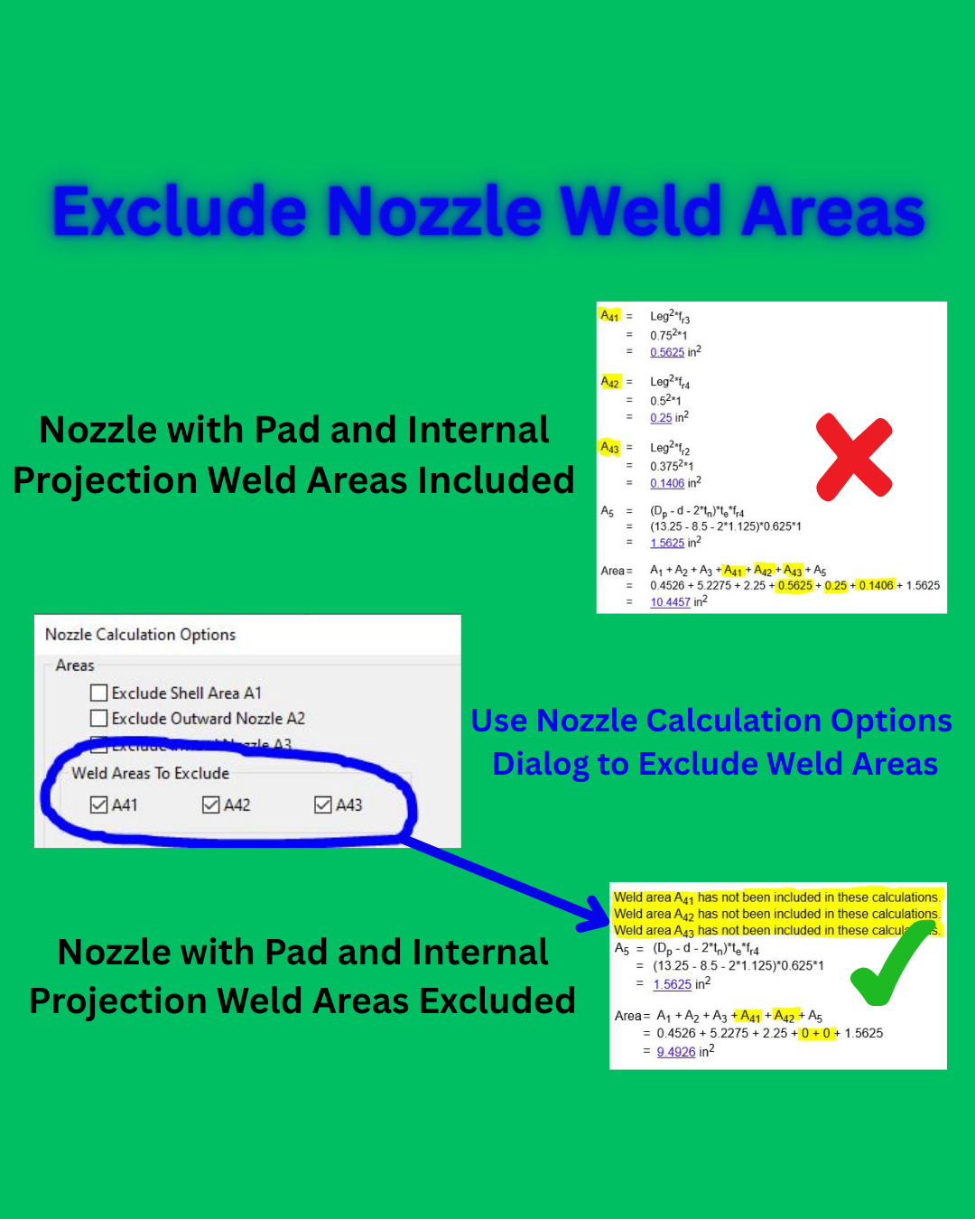
Excluding Weld Areas in UG-37 Calculation
Does your specification sheet require that nozzle weld areas not be included in your UG-37 area of reinforcement calculations?
No problem!
Nozzle and nozzle pad weld areas are easy to remove inside of the Nozzle Calculation Options dialog in COMPRESS. Notice each weld area can be controlled individually, giving maximum flexibility in the calculations.
As we all know, the ASME Code allows weld areas to be included in the area available for reinforcement. However, not all Owner/Operators allow these weld areas to be included in the area available for reinforcement calculations for their equipment. Remove these weld area calculations in COMPRESS without resorting to spreadsheets. Please refer to UG-37 for more information regarding nozzle reinforcement requirements.