
Verify Thicknesses Before Installing Equipment
Do you verify thicknesses before receiving your equipment?
The design calculations use NPS 8 Sch 120.
The fabrication drawings use NPS 8 Sch 120.
You received NPS 8 Sch 80 (XS).
So what happened? A drawing was misinterpreted and a fabrication mistake was made. Fabrication mistakes happen. Don’t compound those mistakes by not finding them until after installation. Using a 3rd party to verify that your as-built thicknesses meet or exceed your design thicknesses is a quick and important step you should implement before receiving your equipment to help improve your bottom line.
I like to use 3rd parties for thickness verification because they are excellent at communicating between fabricators and Owner/Operators during stressful projects. I trust Turnaround EPC for my 3rd party as-built thickness verification because of their excellent communication, fast service, and attention to detail.

Use ASME PCC-1 Appendix O to Fix Leaky Gaskets
Do you have an issue with leaky gaskets?
A lot of people message me complaining about leaky flange gaskets and wondering what kind of gaskets I recommend to help. The fact of the matter is that gasket quality and performance has never been better. I have found that many times the real problem is that the gasket was not considered during the design phase. Gaskets are an important part of flange design. Treat them that way.
Have you performed ASME PCC-1 Appendix O for your flanges?
An approach in ASME PCC-1 Appendix O can help you make sure your gaskets are being seated correctly. The gasket needs to be below the maximum permissible gasket stress, above the minimum seating gasket stress, and above the minimum gasket operating stress. In this example the minimum gasket operating stress is not being maintained at the operating condition.
Make sure you perform ASME PCC-1 next time you open up a pair of flanges.

Consider Longitudinal Stresses in Brittle Fracture Check
Do you consider longitudinal stresses when you check for brittle fracture?
I’ve had a lot of people asking me to check their hydrotest temperatures. A design where a governing longitudinal stress case was not considered in the Minimum Design Metal Temperature (MDMT) stood out to me.
Did you know that longitudinal stresses can govern the MDMT even if circumferential stresses govern the Maximum Allowable Working Pressure (MAWP)? Not checking the longitudinal stresses can lead to devastating results as the brittle mode of failure is swift and catastrophic. Always remember to consider longitudinal stresses in your brittle fracture check.

Division 2 Rules Save $ On Nozzle Design
Did you know you can design safer and save money using ASME Division 2 rules instead of Division 1?
There are many ways to take advantage of the higher allowables and more accurate numerical methods in Division 2. One such method to consider is using the Bildy Rules instead of Area of Replacement for nozzle design.
Take a look at this simple nozzle internal pressure case:
Design Pressure = 290 psi (2000 kPa)
Design Temperature = 475°F (246°C)
Nozzle Material = SA-106 C Smls Pipe
Nozzle Size = NPS 12 Sch 140
The Division 1 vessel does not pass the design condition of 290 psi (2000 kPa) @475°F (246°C).
The Division 2 vessel passes the design condition of 290 psi (2000 kPa) @475°F (246°C).

Move Data from U-Forms into Spreadsheets for AI
Are you ready for AI? Your data is not.
One of the big themes of Reuters Downstream 2025 was the use of AI in maintenance and inspection. I found the concept of using AI for predictive analytics in maintenance incredibly intriguing. However, let’s not pretend that your important data is in a format that AI can actually use. You need to digitize your data.
Are your U-Forms sitting in a filing cabinet somewhere?
How about the historical measured thickness data from internal inspections? Are those values just floating around in PDFs?
What about the interesting information found during external inspections? Repairs? Rerates? Derates? FFS assessments? Wouldn’t you want all of that data digitized in a way that makes it easy for AI to pull from?
We all know that AI is the future but AI is only as good as the data you are feeding it. Consider yourself behind if the items listed above are not in a usable, digital format.

Save $ Using Division 2 External Pressure Rules
Can you save money using ASME Division 2 rules instead of Division 1?
There are many ways to take advantage of the higher allowables and more accurate numerical methods in Division 2.
Take a look at this simple external pressure (vacuum) case:
Outside Diameter, Do = 60.75” (1543 mm)
Thickness, t = 0.375” (9.53 mm)
Unsupported Length, L = 264” (6706 mm)
The Division 1 vessel does not pass the vacuum condition of 14.7 psi (101 kPa).
The Division 2 vessel passes the vacuum condition of 14.7 psi (101 kPa).

Towers Falling During Postweld Heat Treatment (PWHT)
Have you seen a tower fall during Post Weld Heat Treatment (PWHT)?
As crazy as it sounds I’ve seen this occur when PWHT is applied around the circumferential seams of tall towers in the field. The solution is often even crazier as Owner/Operators prefer expensive materials analysis and complex FEA calculations over simple explanations. The fact is the tower behaved exactly as expected as it was never designed to take such loadings at temperature.
So what is actually happening?
1 - The Wind case was not properly considered by the design engineer
2 - The Wind case in the Empty condition was not calculated
3 - The much lower allowable stress in the material at temperature was not considered
4 - Wind loads during PWHT create a large moment that the material was not designed to resist
5 - DOWN IT GOES!!!
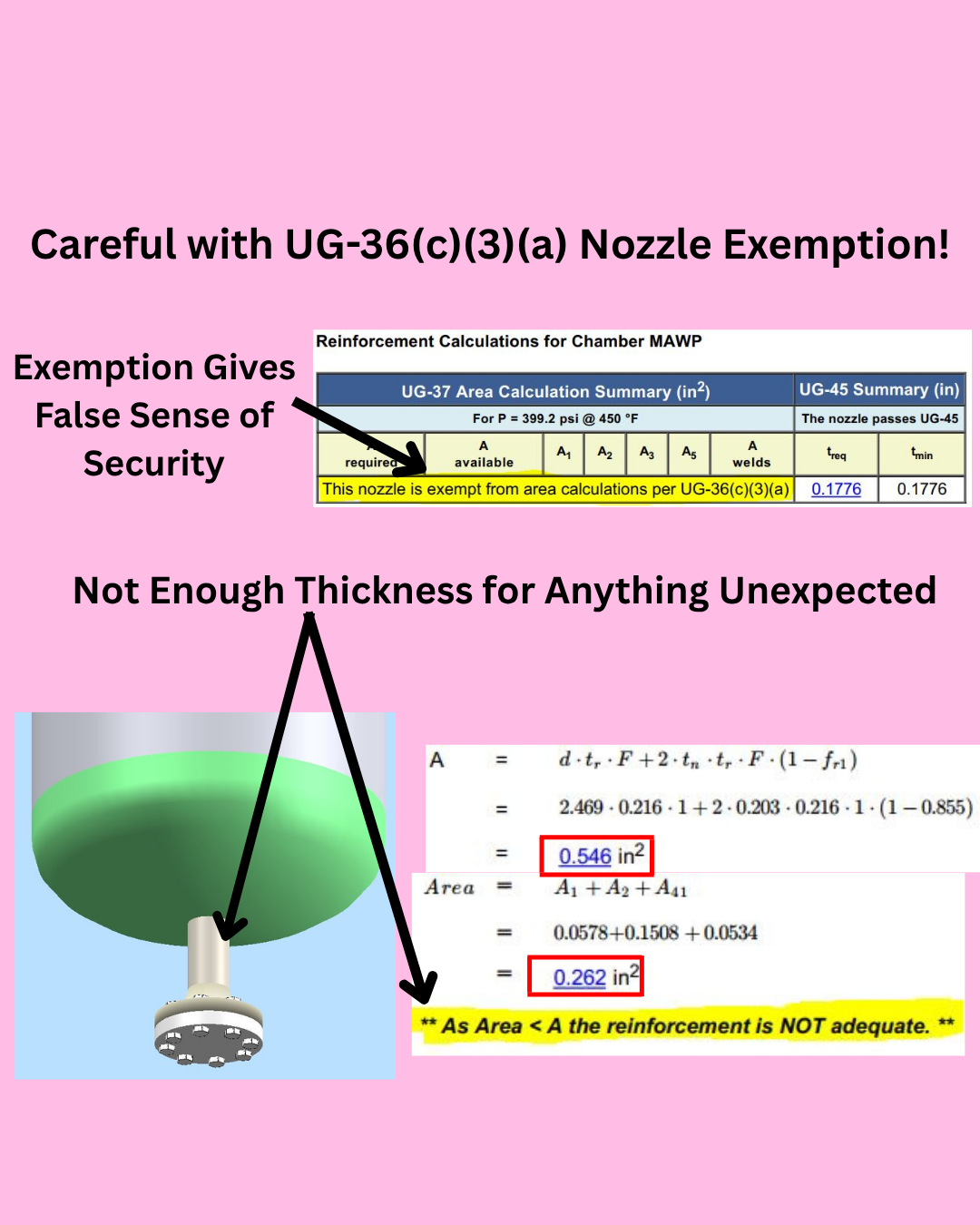
Do Not Use Calculation Exemptions on Important Process Nozzles
Do you use calculation exemptions on important process nozzles?
Yes, we all know nozzles under a certain size are exempted from the Division 1 nozzle area-of-replacement rules. That does not mean that you should use this exemption every time you can. Think very carefully about what each nozzle is used for and what the consequences of failure may be.
You may want to double-check exempted nozzles against another set of nozzle rules before finalizing your design. Are you around 90% of area-of-replacement? Fine. Are you around 50% of area-of-replacement like my example? You may want to add a little thickness to the nozzle. This is a bad place to try to save money on your design.
What if local corrosion is higher than the design corrosion?
There is no nozzle thickness to compensate for corrosion. Through wall corrosion is common.
What if nozzle loadings are higher than anticipated?
There is no extra thickness to handle pressure plus unexpected loadings.
What if an upset condition increases the process velocity?
There is no extra thickness to handle process erosion.
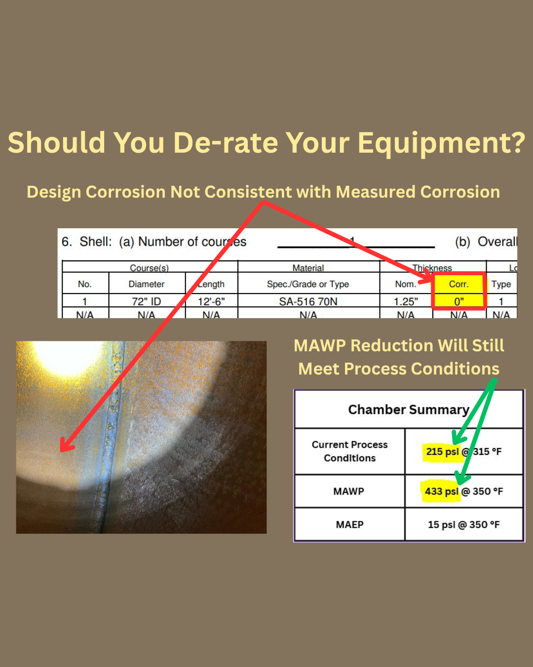
Derating for Process Safety Reasons
Why would anyone de-rate a pressure vessel or heat exchanger? What is the point of formally accepting less out of your equipment than it was designed for?
The simple answer is to reduce the operational risk at your facility by ensuring that pressurizing to the original Maximum Allowable Working Pressure (MAWP) is never attempted. The most common scenario I observe is when a design with no corrosion allowance does not align with measured in-service corrosion.
Many times pressure vessels and heat exchangers operate much lower than their ratings so de-rating causes no operational disruptions. Is there any equipment in your facility that could use a de-rate?

Be Careful with RT-4 Vessels in Corrosive Service
I think it’s time we talk about “RT 4” vessels and heat exchangers. I see them everywhere in corrosive processes and highly consequential service and I really wish I didn’t.
So what is “RT 4”? Well “RT 4” simply means that “RT 1”, “RT 2”, or “RT 3” do not apply. It does not mean anything else specifically about what kind of weld inspection was applied to the vessel.
How much radiography or other weld inspection is applied to a vessel marked “RT 4”? Some? None? I don’t know, but probably not a lot. I personally assume that no weld inspection was performed unless proven otherwise. This is where I have a problem with “RT 4” vessels and exchangers. I don’t feel comfortable placing vessels and heat exchangers in service without having some sort of assurance regarding the quality of the welds. When I uncover the root cause of unplanned shutdowns too many times these “RT 4” vessels are to blame.
I consider the cost of maintenance and inspection in my designs and I do not believe any money is saved in the long run by operating “RT 4” vessels.
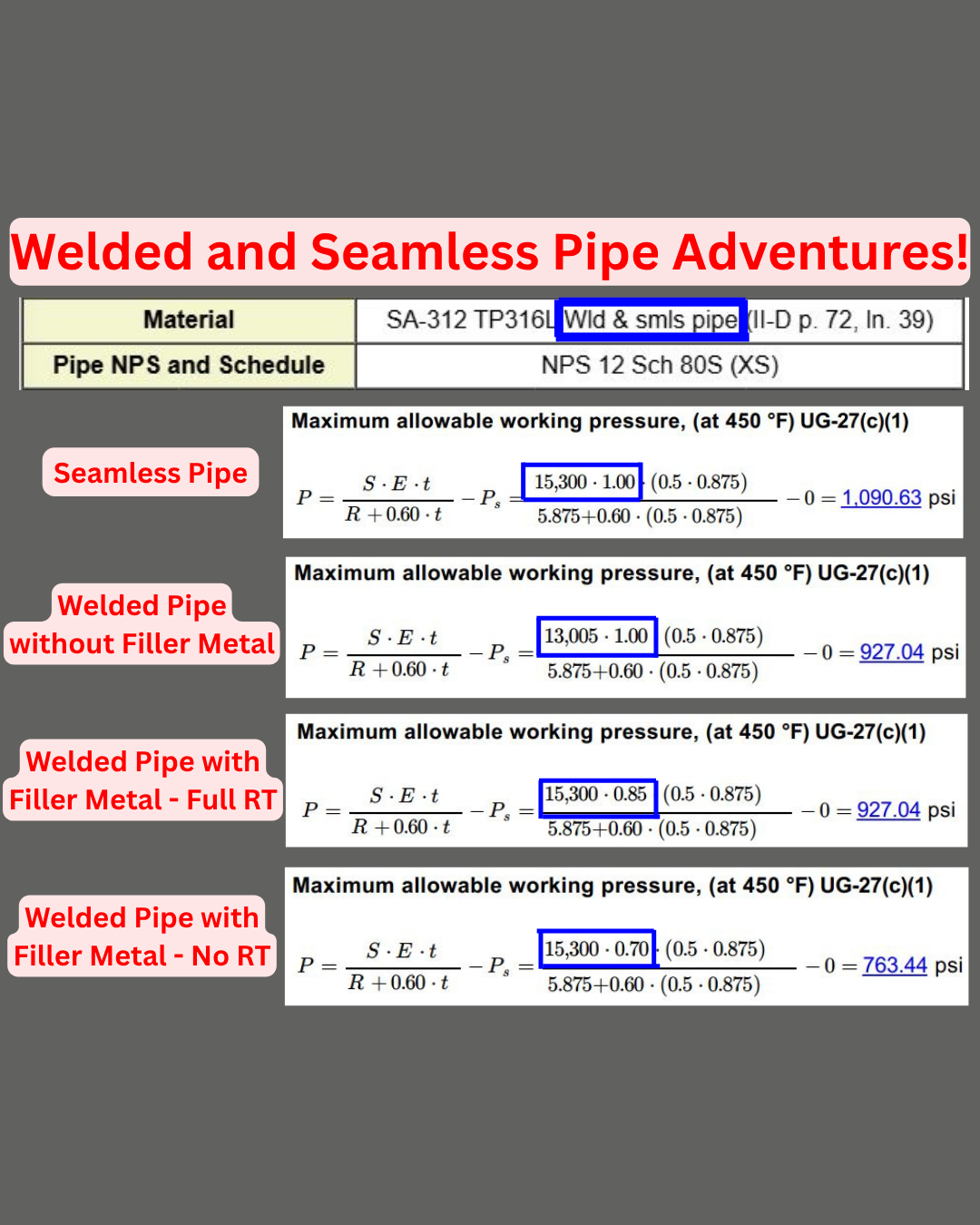
“Welded and Seamless Pipe” Product Form
Let’s talk about my favorite product form “Welded and Seamless Pipe”.
Is it Welded? Is it Seamless? Is it Both? Wait, that’s impossible…
Well then what is a “Welded and Seamless Pipe”? I have no idea. What I do know is that there is a big difference between how welded pipe and seamless pipe are handled when it comes to ASME Code calculations. You need to know exactly which version of the material you have before performing calculations or there is a good chance you will be making a big mistake.
Let’s take a look at SA-312 TP316L, which includes the seamless and welded pipe product form in the same specification.
Seamless: No need for a longitudinal weld joint efficiency factor in the allowable stress. Double-check to make sure the allowable stress reflects this.
Welded Pipe Made without Filler: The longitudinal weld joint efficiency factor needs to be included in the allowable. Notice the allowable is (15,300 x 0.85 = 13,005). There is no need to count this twice and multiply by 0.85 again in the joint efficiency value.
Welded Pipe Made with Filler: The joint efficiency factor was not included in the allowable so it needs to be taken into consideration in the joint efficiency value itself. Keep in mind that the joint efficiency value may be lower than 0.85 depending on the radiography performed.
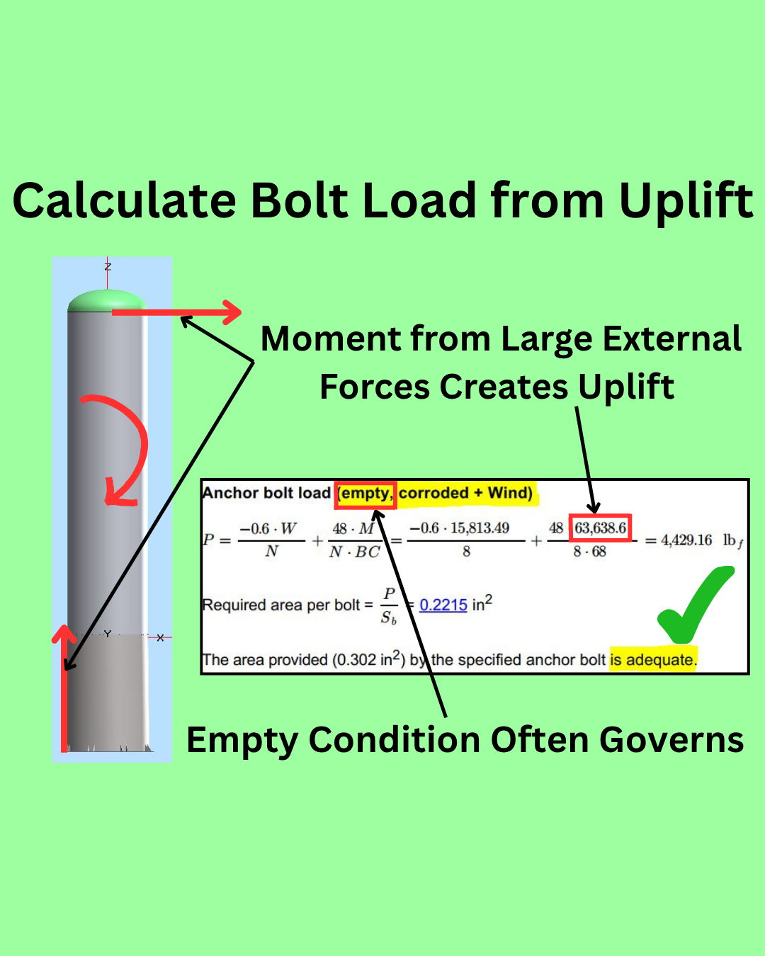
Calculate Uplift for Bolting
Are your bolts designed to handle the uplift from moments caused by external forces like wind and seismic loads?
I commonly see equipment where only the operating case is checked and I’ve even seen cases where the bolt uplift calculation is ignored altogether. Don’t be fooled into ignoring this simple calculation as catastrophic bolt failure can cause severe damage to your equipment.
The empty condition often governs because process weight helps to prevent uplift. Please calculate all design conditions to determine the governing case.

Mechanical Credit for Cladding
Are you getting the credit you deserve?
The ASME Code allows you to take mechanical strength credit for cladding in design calculations. Most design engineers do not take credit for cladding and end up purchasing a thicker shell than necessary.
Take a look at this simple internal pressure with cladding example:
Design P = 350 psi (2413 kPa)
Shell Material = SA-516 70
Cladding Material = SA-240 316L
MAWP from shell component: 343 psi (2365 kPa)
MAWP from cladding component: 40 psi (276 kPa)
MAWP from shell plus cladding: 383 psi (2641 kPa)
Using only the shell component for mechanical strength fails at the Design Pressure of 350 psi (2413 kPa).
Using the shell plus cladding for mechanical strength passes at the Design Pressure of 350 psi (2413 kPa).
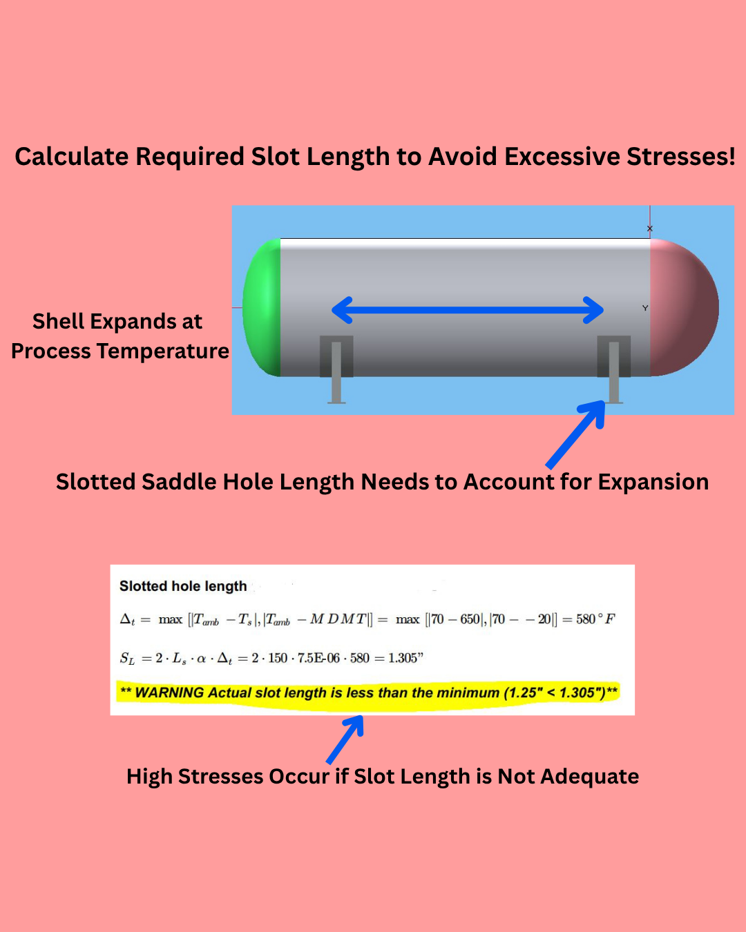
Calculate Required Slotted Bolt Hole Length
Can your saddle bolt holes handle the effects of thermal expansion in your equipment?
Bent saddles and sheared bolts from undersized slotted bolt holes pose a major operational risk that is often overlooked. It is much easier to design for thermal expansion before fabrication than it is to try to fix an inadequate slotted bolt hole length while in service. There is a simple calculation to determine if your slotted bolt hole length is enough to handle thermal expansion at design temperature.
Please review PIP VEFV1100 for more information regarding the design of supports and other attachments.

Check Water Temperature Before Hydrotest
Please check the water temperature before performing your hydrotest. It may be too cold!
Have you ever seen a pressure vessel or heat exchanger crack due to brittle fracture during hydrostatic testing? Thousands of hours spent on calculations, drawings, welds, and inspections down the drain. Then the root cause investigation results in more time and money lost.
Brittle fracture can occur during hydrostatic testing when the water temperature used in the hydrotest is too close to the Minimum Design Metal Temperature (MDMT) of the material. This means that your equipment can pass the design MDMT calculations and still experience brittle fracture during hydrostatic testing. This simple temperature check is often missed and can lead to devastating results.
Please review UG-99 for more information regarding hydrostatic testing.

LWN Forged Flanges Required Nozzle Calculations
Are you performing the required calculations for your LWN forged flanges?
LWN forged flanges are popular among Owner/Operators because the ASME Codes offer some calculation exemptions. However some Owner/Operators have started to believe that LWN forged flanges are exempt from all calculations. This is a dangerous trend as LWN forged flanges are not automatically acceptable at their designated ASME B16.5 flange pressure rating classification. Yes, LWN forged flanges do have some similar exemptions as ASME B16.5 flanges but a full nozzle calculation must still be performed at the nozzle-to-vessel intersection.

Performing Proper Hydrotests After Tube Bundle Replacements
Are you performing proper hydrotests after Tube Bundle Replacements?
I’ve seen some interesting ways Owner/Operators try to save money on new equipment costs. Opting for leak tests and proof tests instead of performing ASME Code required hydrotests has become increasingly popular, especially when it comes to tube bundle replacements. The problem with not performing a full hydrotest at the fabrication shop is that the requirement to field hydrotest is hidden away as a remark at the end of the U-Form and is easily ignored.
Owner/Operators have not yet made the connection between the frequency of their tube bundle replacements and the lack of proper hydrotest for the tube bundles they are replacing. Properly hydrotested tube bundles will last longer. The most cost effective way to perform your hydrotest is most often at the fabrication shop. Please pay your fabricator for a full hydrotest.

Integrally Reinforced Nozzles
While visiting a client I was pleasantly surprised to see several tanks constructed with integrally reinforced nozzles. Everyone knows that I like to avoid designing with nozzle pads whenever possible. Integrally reinforced nozzles give the additional reinforcement necessary to resist membrane stress at the nozzle intersection without the negative repercussions of using nozzle pads.
In the past I had to use spreadsheets to manipulate the nozzle calculations to account for integral reinforcement. Now I can easily model these nozzles with the “Insert (Q) Lip” option in COMPRESS.
Notice that I don’t give up much stress resistance by using a 12” integrally reinforced nozzle over a 12” nozzle with nozzle pad.

Do You Need to Multiply Welded Pipe Allowables by 0.85?
Do you need to multiply welded pipe material allowables by 0.85?
I get a lot of questions regarding the allowable stresses for various material product forms. The one I’ve been asked about a lot recently is whether or not the allowable stress for welded pipe needs to be multiplied by 0.85.
The answer is, probably not, but it depends. You really need to take a look at the material notes for your welded pipe material in ASME Section II, Part D. This will reveal whether or not the lookup allowable in ASME Section II, Part D has already been multiplied by 0.85. Let’s take a look at a couple of the notes in Table 1A:
G24: This note indicates that the 0.85 has already been applied to the allowable stress. You do not need to multiply the allowable stress by 0.85 again. In this example the allowable stress lookup of 14,600 psi can be used directly in circumferential stress equations.
W12: This note indicates that the 0.85 has not been applied to the allowable stress. You need to multiply the allowable stress by 0.85 if the welded pipe was created without using filler metal. In this example the lookup of 21,400 psi was multiplied by 0.85 to achieve the 18,190 psi allowable used in the circumferential stress equations.
The ASME Section II, Part D material notes are not just informational, they can directly affect the allowables you used in stress equations.

Allowable Stress Rounding Rules Changed in 2007
Did you know that the rounding rules for allowable stresses in ASME Section II-D changed in 2007?
If you are anything like me you have to run a lot of calculations on older equipment. Making sure I use the correct allowable stress is not always a straightforward task. One ASME Code change I have to remember is to the rounding rules in the 2007 version of ASME Section II-D.
In this example using the latest allowable stress rounding rules results in an unconservative required thickness because the original design was calculated using a lower allowable stress. Please do not accidentally give yourself credit for the newer allowable stress rounding rules when re-calculating older equipment.