
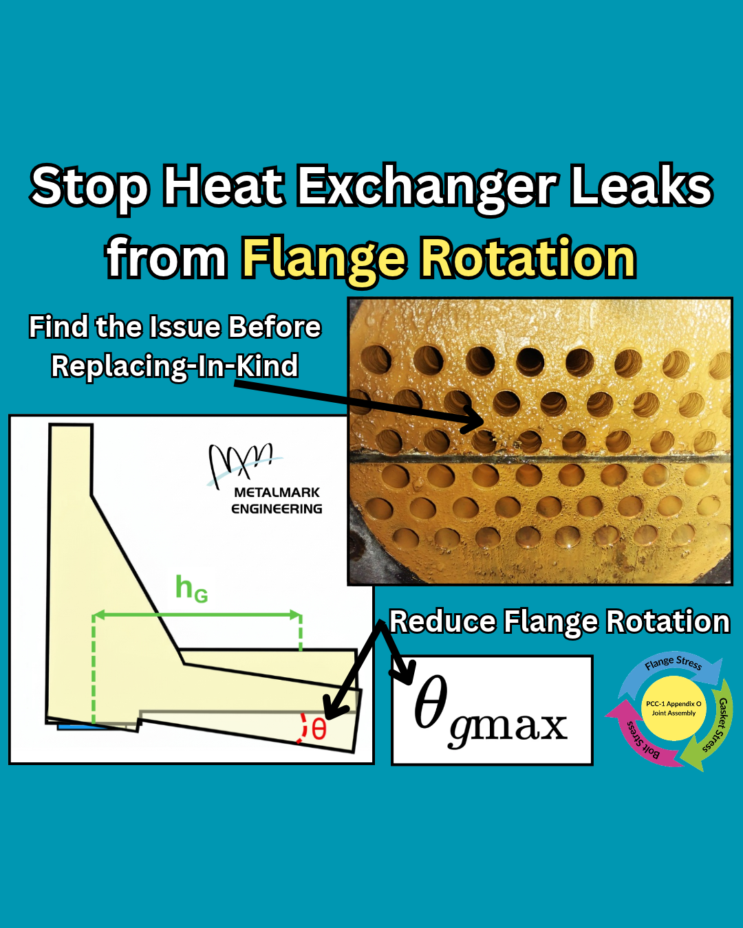
Heat Exchanger Leaks from Operational Flange Rotation
Having issues with your heat exchanger leaking at the tubesheet flanges? Flange rotation at the Moment Arm, hG, may be the root cause!
Replacing the tube bundle in-kind and using the same bolt torque values is the typical solution for solving heat exchanger leaks. However, a new tube bundle may not solve problems from flange rotation because the issue may be with the design. In fact, I’ve seen facilities replace the same tube bundles every 6 months for decades! A couple of simple checks can save a huge headache.
Please check these two cases to ensure that the flange rotation limit is not exceeded in your design:
Thermal expansion through the flange and hub. Flange rotation caused by thermal expansion is especially important in heat exchangers because leaks around the pass partitions become more likely when the rotation limit is exceeded.
Differential pressure across the tubesheet. Many times flange rotation caused by differential pressure loading cannot be rectified by simply updating the bolt torque values. I often propose a redesign instead of replacing-in-kind for these cases because increasing the tubesheet thickness greatly reduces the flange rotation.
I recommended checking if the flange rotation limit is exceeded for your heat exchanger design by calculating the Maximum Permissible Bolt Stress Prior to Flange Damage, Sfmax, using the correct Maximum Permissible Flange Rotation, 𝛳gmax, for your gasket type, and determining an appropriate Single Flange Rotation at Sfmax, 𝛳fmax, for your design per PCC-1 Appendix O.
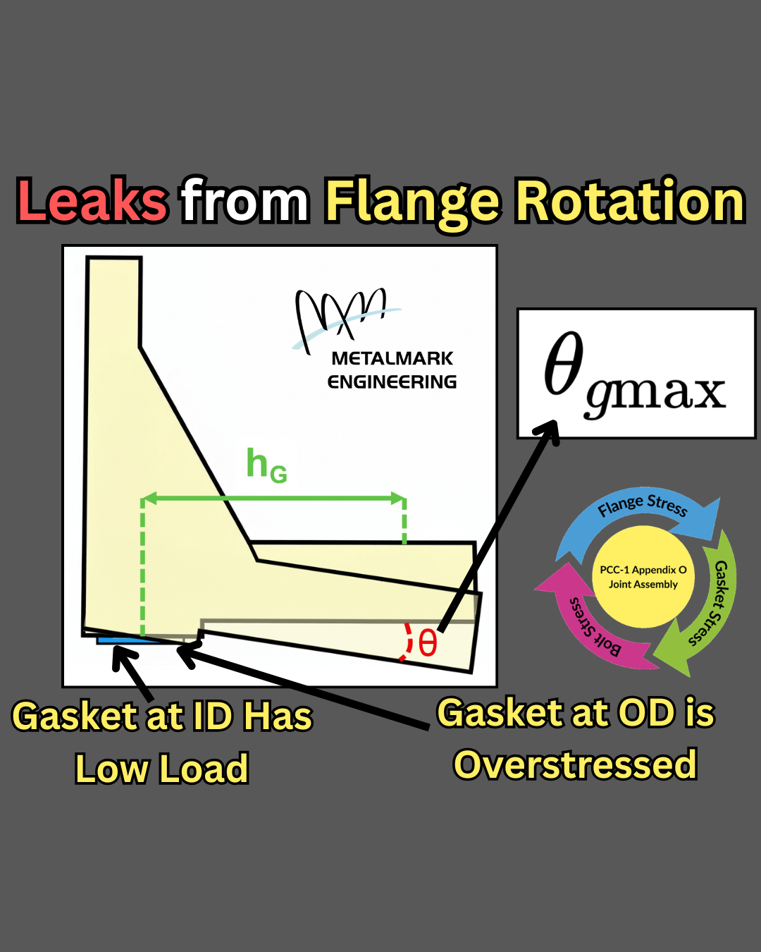
High Operational Flange Rotation Can Cause Leaks
What is operational flange rotation? Operational flange rotation occurs when bolt load plus thermal expansion through the flange and hub causes the flange to rotate at the Moment Arm, hG, at the operating temperature. Excessive rotation around the Moment Arm, hG, causes uneven gasket loading between the inner and outer gasket diameters. In extreme cases the gasket at the inner diameter may experience no load while the gasket at the outer diameter is crushed and destroyed.
A perfect recipe for a leaky bolted flange connection!
Leaks caused by operational flange rotation are often difficult to diagnose and even more difficult to remediate. This is because the first solution is usually tightening the bolts to a higher torque, which will make the problem worse.
Please pay attention to Maximum Permissible Flange Rotation, 𝛳gmax, and the Single Flange Rotation at Sfmax, 𝛳fmax, per ASME PCC-1 Appendix O for your bolted flange connections, especially for processes at elevated temperatures.

Hub Length Impacts Sfmax
Flange hub length has a big impact on the Maximum Permissible Bolt Stress Prior to Flange Damage, Sfmax. Make sure you get it right.
I’ve presented ASME PCC-1 Appendix O to facilities all across the United States. One not-so-obvious mistake I’ve found reviewing their torque tables pertains to the flange hub length. Let’s go over a couple of issues:
One facility assumed no flange hubs in the Sfmax calculation for their welding neck flanges. This ensures that the effect of Longitudinal Hub Stress, SH and Radial Flange Stress, SR cannot govern (because they are not calculated). This approach is not recommended as it does not represent reality and is unconservative.
Another facility assumed full length hubs for their ASME B16.5 flanges in the Sfmax calculation when shorter hubs were actually used in the plant. The shorter flange hubs still complied with ASME B16.5 but meant they could not rely on the standard torque tables they were using.
Is anyone reviewing the torque tables at your facility? Today is a great day to get your review started.

Sfmax Made Easy
We need to have a heart-to-heart talk about the Maximum Permissible Bolt Stress Prior to Flange Damage, Sfmax.
I see a lot of really high “default” values to make sure it never governs the Selected Assembly Bolt Stress, Sbsel inside of the ASME PCC-1 Appendix O calculation. This is an unconservative approach because it ignores the actual flange stresses that can be attributed to leaky gaskets.
I prefer that the Target Assembly Gasket Stress, SgT governs the Selected Assembly Bolt Stress, Sbsel instead of Sfmax inside of the ASME PCC-1 Appendix O calculation. In other words, I do not want the flange to yield before the gasket seals properly. That is exactly why I like to make sure I calculate an accurate Maximum Permissible Bolt Stress Prior to Flange Damage, Sfmax value by iterating on all seven flange stress combinations.
The Maximum Permissible Bolt Stress before Flange Damage, Sfmax governs the bolt stress applied to the bolted flange joint assembly for many Class 150 and Class 300 standard ASME B16.5/16.47 flanges. 𝐏𝐥𝐞𝐚𝐬𝐞 𝐝𝐨 𝐧𝐨𝐭 𝐨𝐯𝐞𝐫𝐥𝐨𝐨𝐤 𝐭𝐡𝐞 𝐒𝐟𝐦𝐚𝐱 𝐜𝐚𝐥𝐜𝐮𝐥𝐚𝐭𝐢𝐨𝐧 𝐟𝐨𝐫 𝐀𝐒𝐌𝐄 𝐬𝐭𝐚𝐧𝐝𝐚𝐫𝐝 𝐟𝐥𝐚𝐧𝐠𝐞𝐬.

Sfmax Governing Bolt Stress
Flanges yielding before the gasket is properly sealed?
That is what you are risking when you allow Sfmax to govern the Selected Assembly Bolt Stress, Sbsel inside of the ASME PCC-1 Appendix O calculation. Please reconsider flange selection if the Maximum Permissible Bolt Stress before Flange Damage, Sfmax is limiting the bolt torque applied to the bolted flange joint assembly.
It is important to understand the seven load combinations included in the WRC 538 analysis. That is why Metalmark Engineering created this flange diagram to help visualize what each of the seven flange load combinations are checking for. I find it to be helpful when trying to investigate which load(s) is governing the Maximum Permissible Bolt Stress before Flange Damage, Sfmax.
The Maximum Permissible Bolt Stress before Flange Damage, Sfmax governs the bolt stress applied to the bolted flange joint assembly for many Class 150 and Class 300 standard ASME B16.5/16.47 flanges. 𝐏𝐥𝐞𝐚𝐬𝐞 𝐝𝐨 𝐧𝐨𝐭 𝐨𝐯𝐞𝐫𝐥𝐨𝐨𝐤 𝐭𝐡𝐞 𝐒𝐟𝐦𝐚𝐱 𝐜𝐚𝐥𝐜𝐮𝐥𝐚𝐭𝐢𝐨𝐧 𝐟𝐨𝐫 ASME standard 𝐟𝐥𝐚𝐧𝐠𝐞𝐬.

Flange Yield Stress at Ambient and Operating Temperature
Does temperature matter for bolting flanges?
I am often asked which flange yield stress value to use in the ASME PCC-1 Appendix O calculation. On one hand using the ambient air temperature makes perfect sense because it is the temperature the flange is assembled at. On the other hand using the operating temperature makes sense because higher temperatures can significantly lower the yield stress. The fact is that both need to be considered before selecting the Yield Stress (Sy) used in the determination of the Maximum Permissible Bolt Stress before Flange Damage, Sfmax.
The Modified Yield at Operating (S’yo) often governs over the Yield at Assembly (Sya) if:
Fraction of Gasket Load Remaining after Relaxation (ϕg) is close to 1
The the Yield at Operating (Syo) is 12.5% less than the Yield at Assembly (Sya)
This means that flanges with spiral wound gaskets and flanges operating at temperatures much greater than assembly temperature are susceptible to the Modified Yield at Operating (S’yo) governing over the Yield at Assembly (Sya). Please consider both assembly and operating temperatures when selecting the Yield Stress (Sy) used to find Sfmax.